The easiest way to fix this bug is to simply remove the 74LS138 from its socket, slightly bend pin 1 out so that it will not go back in and put the 74LS138 back into the socket. run a wire from pin 1 on the 74LS138 that is now sticking out and pin 4 on the EPROM. You can solder directly to the chip and this will fix the problem. Pin 1 must be removed from VCC to fix this problem. Just soldering it to pin 4 on the EPROM will not resolve this issue and will infact create a new problem.
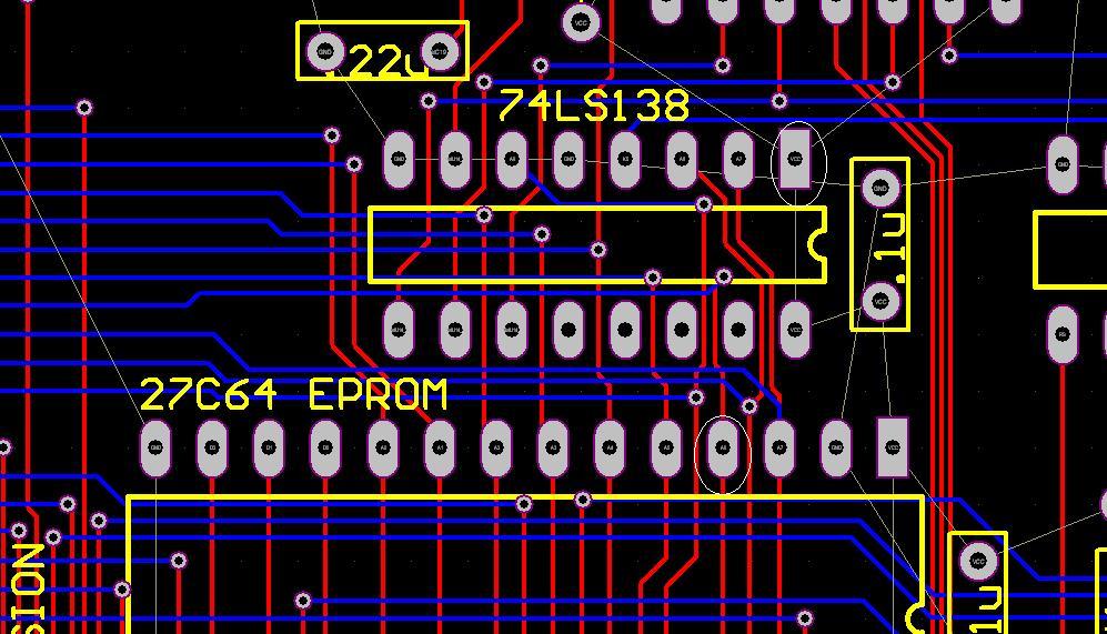
Looking at the image above you see a drawing of the Micro-KIM board in the area discussed. The two pins that need to be connected are circled.
Ok, so lets say you are really good with soldering and you have a want something that doesn't show as much. Here is a picture showing where a through hole is located to connect pin 1 on the 74LS138 to.
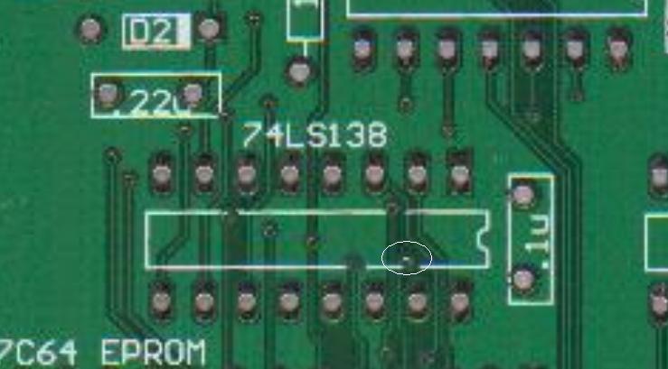
Ok, so here is the trace Address pin A6 through hole as shown from above on a bare board. You can run a wire from here to PIN 1 on the 74LS138 (not on the board but the removed pin) and this will resolve the issue.
Part 2 of fix:
After working on the first bug, a 2nd part was discovered. This fix requires cutting 2 traces on the pcb and adding 2 wires. This is a pretty straight forward fix. First, look at the top of the board and find the 74LS00 just below the DB9 RS232 connector and the resistors.
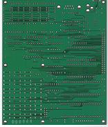
Click on the image above to see a full size picture of a blank board. Locate the arrow pointing to the area where the cut needs to be made. The trace to cut has a small white line going thru it. Use an exacto or small knife and carefully cut the trace. If you go a little over into the 5V pour area around it, that is ok, just don't cut any other traces. Check that cut with an ohm meter to make sure the trace is cut completely.
Next, turn the board over and look at the same chip on the bottom and use the picture below to help with the next step.
On the bottom you will need to locate the arrow pointing to the area to work on. Now locate the small white line. That is the trace that needs to be cut. Once again, use caution not to cut other traces in the area but the ground plane around it is ok if it gets cut a little. Now you will see 2 yellow lines, these are where you need to add jumper wires. You can use very small guage wire and run wire to these two places.
The last section requires one more cut and wire. As you can see in the picture below, cut the trace on the bottom of the board with the exacto or knife that is marked in white. Run a wire like the yellow line to the new location.
This fixes the upper 64 bytes of RAM in the 6532 to function properly and is required for complete KIM-1 software compatibility.
If you don't feel comfortable with doing this fix, please contact me and arrange to ship it to me and I will apply the fix at no charge. |